
|
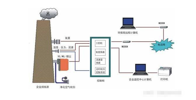
The latest continuous monitoring system for flue gas emissions CEMS transport shallow analysisTime: 2021-12-08 CEMS is an important online instrument for the proper operation of power plants and the monitoring of the transmission of environmentally friendly data, which is used primarily in denitrogenization and desulphurization systems. The main equipment of CEMS for desulphurization, denitration systems is a smoke-discharge analyzer, sampling unit, pre-treatment system, dust unit, ammonia escape measurement unit, PLC control system, data collector, communication transmission equipment, etc. The main monitoring parameters are SO2, NOX, O2 smoke flow speed, smoke discharge temperature, smoke discharge pressure, dust concentration, NOX, O2, ammonia escape, etc.
1CEMS status. 1.1 CEMS applications in production control. There are two CEMSs in the devulcanization system, which monitor primary and clean smoke, respectively. The parameters measured by the original smoke CEMS are provided to the automated control system as a front feed signal, the parameters measured by the clean smoke CEMS are provided to the automated control system as a feedback variable and the corresponding equipment is controlled more effectively through the back and back data. Data from CEMS monitoring of emission vents is sent to the environmental protection sector. 1.2 CEMS system process. Smuggled the smoke gas in the smoking lanes, followed by sampling probes, sampling lines, primary filters, primary filters, primary filters, primary filters, secondary condensation, secondary filter pre-procession, and gas analyzers after sampling pumps, water extraction filters.
2 Common malfunctions and solutions in operation. 2.1 Analysis and processing of causes of data anomalies. According to the CEMS process, failure at any point leads to an anomaly in the measurement data. When data anomaly occurs, a preliminary determination is made based on the actual situation, from the parts with the greatest probability of failure to the proper operation of the equipment. (1) The analyzer ' s zero point or range drift. The analyzer ' s zero point or range drift cannot be visualized and can only be judged by a comparative analysis. (2) The analyzer shows that the oxygen is greater or less than normal. When the oxygen measure is higher than normal, check if the sampling pipe is leaking; check if the oxygen sensor is normal when the oxygen is low or not visible, or replace it. (3) The moisture content in the airways is high. Checks whether the sampling probe and the heating of the coheated pipe are working and excludes the moisture in the pipe. (4) The breakdown of the analyzer. The damage to the analyzer, in addition to the ageing of the equipment, is not well prepared for multi-body pre-treatment. 2.2 Fluxes abnormal. The flow anomaly is generally shown to be below normal or non-flow. When checking whether the rotor flow meter is blocked, check if the sampling pipe as a whole is leaking or blocked. 2.3 Temperature, pressure, flow data anomalies. Checks whether the corresponding measurement elements are normal and whether the sampling pipe is open. 2.4 The values of the ammonia escape measurements are abnormal. Check if the ACAF energy values are normal, if the probes are ash-filled, if the light is normal, and if the Sealed Wind Blower is working. 2.5 The measurements of particulate matter are abnormal. Check if the vacuum cleaners are running properly, if the vacuum cleaners are damaged, if the lenses are clean or if the compressed air for clean disposal is properly injected. 3 Attention during maintenance. In order to ensure that CEMS measurements are accurate and reliable, daily inspections of CEMS equipment are conducted, historical data and data reports are viewed, anomalies in equipment are detected and removed in a timely manner, and the system is more reliable. We need to perform the following daily maintenance tasks: 3.1 Periodically marked analyzers. The analyzer regularly carries out zero-point calibration and Quantification. CEMS small rooms are equipped with three lower standard concentrations of gas and high-purity nitrogen in high schools for each tested medium factor, and are marked and compared by another standard concentration. At least once a half-yearly period. Automatic zero-point calibration is designed to automatically mark zero points for 8 to 12 hours, based on the actual situation of the equipment on the ground, in order to avoid zero-point drift and to ensure the correctness of the analytical determination. 3.2 Consistency in the range of parameters. In the selection of analyzers and standard gases, the scale range of the analyzer shall be based on the design concentration of the medium factor measured in the flue gas, which shall generally not exceed twice the maximum emission from the source, and the selection of the standard gases to ensure the accuracy of the analyzer measurements shall be based on the analyzer ' s scale and measured concentration of the medium factor, and shall not be excessive or too low. The measurements of the upper jet, the PLC and the data collector must be set in a consistent manner. 3.3 Heating and refrigeration units. Heating and refrigeration units are important equipment for the protection analyzer and are the focus of day-to-day patrols and maintenance. The temperature of the heating device is generally controlled at about 130 °C and, in the absence of heat, the moisture in the flue gas enters the analyzer, filter core jams, damage to the analyzer, etc., while the pipe forms acid fog, and the temperature of the chiller device directly affecting the determination is generally controlled at around 4 °C and the temperature of the condensation device at more than 6 °C requires repair or replacement. 3.4 Counter-blow system inspection. The automatic reflection is the setting of a reflection time in the PLC control system to maintain the measurement data and does not result in abnormal or equipment damage to the control system due to a reflection. 3.5 Pump inspection. Wrinkle pumps are used to drain water from the refrigerator condensation drums and sealed sampling airways. (a) When the creep pump is not working for a long time, damage to the equipment is caused by the entry of water into the sampling pump and analyzer; The sampling pipe is not sealed and measurements are unusual when the pumps are damaged. 3.6 Sample pump inspection. Sample pumps are important equipment for CEMS, often with side valves installed on the sample pumps, reducing the load of the sample pumps and extending the lifetime of the sample pumps. 3.7 Filter checks. The primary, secondary and hydrophobic filters remove moisture and impurities from the sample gas. Replace the filter elements regularly, typically every 3–6 months. 3.8 Sampling probes. Regularly check the sampling probe heater and inspect the probe filter for blockages. Clean dust from the probe elements periodically and replace severely clogged elements. The typical replacement interval is 6 months. 4 Concluding remarks. CEMS works in poor working environments, complex systems, and inevitably suffers from a variety of malfunctions in day-to-day operations, making the proper determination of the cause of the malfunctions, which can be handled quickly. A certain amount of experience has been accumulated over the course of many years of operation, and is now shared for your information in the maintenance process. |